The Ex-i type of protection: intrinsically safe certified constructions
In an intrinsically safe electrical system, the electrical devices that can be installed in the hazardous area can be simple constructions or constructions certified as intrinsically safe. The first can be passive components, components with well-defined stored energy or with limited energy generation. The latter are more complex ...
by Andrea Battauz, R&D Manager of Cortem Group
Premise
In an intrinsically safe electrical system, the electrical devices that can be installed in the hazardous area can be simple constructions or constructions certified as intrinsically safe.
The first can be: passive components, components with well-defined stored energy or with limited energy generation.
The latter are more complex objects that must be evaluated in such a way as to allow any arc not to exceed specific energy limits related to the gas group. They therefore require certification and the regulation that guides the development of these circuits is the IEC 60079-11 standard in the IECEX scheme and the EN 60079-11 standard in the world of the ATEX directive.
In this set of equipment, we find instrumentation, which, by itself, operates with low voltages and currents and can be easily designed following the principles of intrinsic safety. Common applications of this type of protection are signal transmitters, I/O converters, detectors, solenoid valves and portable instruments.
The energy required to ignite a gas mixture and gas groups
When we state that the intrinsically safe protection method is based on the limitation of the electrical and thermal energy of the installed devices, we must examine how some gases are easier to ignite than others (a similar argument could be made for dusts).
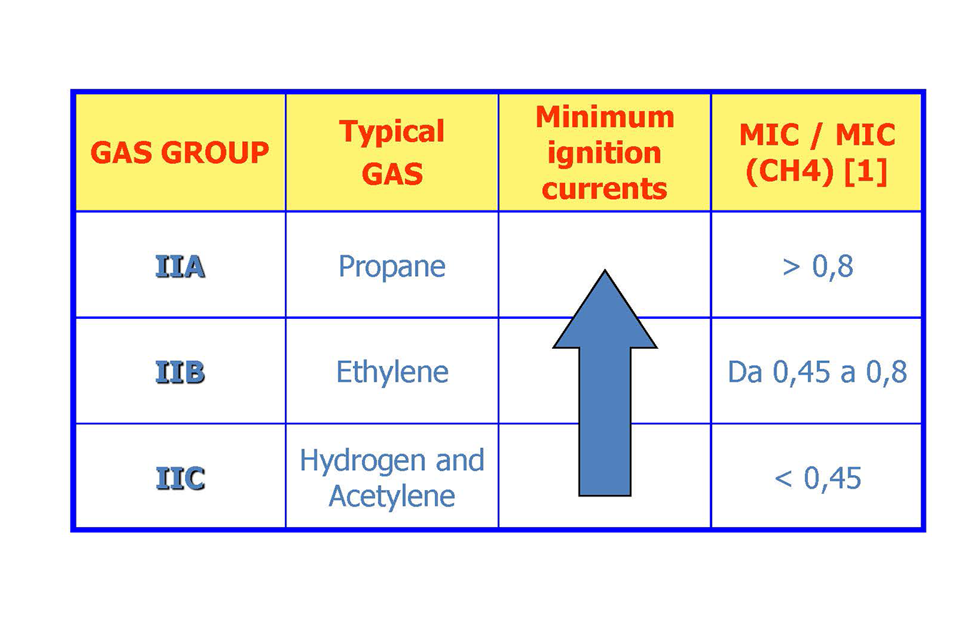
There is therefore a standardised electrical circuit which allows the minimum ignition current of a certain gas to be determined, this is then expressed as the MIC/MIC (CH4 ) ratio, or the ratio between the minimum ignition current of the gas and that of METHANE [1].
Here we find the concept of Gas Group with which the standard offers us a classification of Gases in 3 different groups: IIA, IIB and IIC. The ignition current, as we can appreciate from figure 1, is greater when passing from Group IIC to Group IIA. This means that, similarly to what happened for the Ex-d explosion protection method, it is more problematic to manage a substance belonging to the IIC gas group than one from the IIA gas group.
The level of protection of intrinsically safe certified constructions
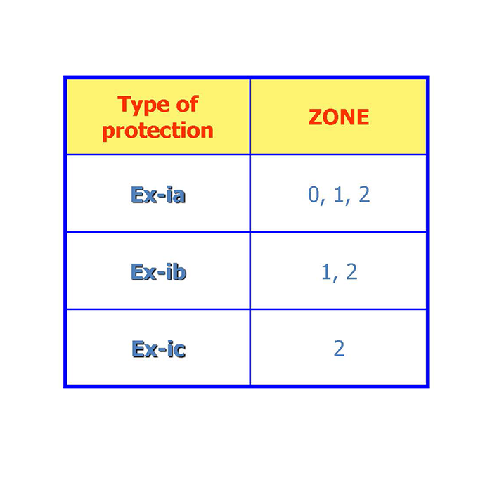
Intrinsically safe circuits have various levels of protection. Each of them can be installed in Zones with greater possibilities of formation of explosive atmospheres. The lowercase letter “a” represents the level of protection Ga and similarly the letters “b” and “c” the levels of protection Gb and Gc.
The design for the various levels of protection therefore also takes into consideration safety in the event of one or more faults [2]. We could consider the Ex- ia protection mode to be safe in the event of two faults, Ex- ib to be safe in the event of one fault, Ex- ic to be safe in normal operation.
The characteristics of intrinsically safe certified constructions
Intrinsically safe certified constructions are characterized by the level of protection (ia, ib and ic) and by the gas group IIA, IIB or IIC. However, it should not be forgotten that in a hazardous area, the temperature that the equipment could reach in normal operation, or where required, following expected failures, must also be considered. Therefore, the temperature class (T1, T2,...T6) will also be indicated in the marking.
For example, a marking like: Ex ib IIB T5Indicates an intrinsically safe construction with EPL Gb (Zone 1 or 2), suitable for gases of group IIB or IIA with an ignition temperature above 100°C [3].
In addition to these parameters, there are other characteristics of this type of protection:
-Ui maximum applicable voltage-Ii maximum applicable current
-Pi maximum dispersible powerWhich represent the maximum voltage, current and dissipated power applicable to the equipment, while
-Li Equivalent internal inductance
-Ci Equivalent internal capacity
these are parameters necessary for the global analysis of the system and represent equivalent values of the equipment. [4]
Conclusions
Within a plant classified for the possible formation of an explosive atmosphere, the intrinsic safety protection mode Ex “i” is widely used in the measurement and process control sector. The great development of electronics in the second half of the twentieth century, which is based on the use of extremely low electrical current and voltage values, has led to an ever-increasing application of this protection mode.
Notes and bibliographical references
[1] Explosion Protection – Heinrich Groh page 104 Table 4.3
[2] The IEC/EN standard makes a distinction between “countable” and “non- countable” faults. This discussion does not intend to go into too much detail.
[3] Gas group, EPL and temperature class follow the rules of tables 1, 3 and 4 of CEI EN 60079-14:2015-04. As regards the temperature class, unless otherwise specified, it is to be understood as referring to Tmax, amb = 40°C.
[4] an electric circuit can always be reduced to a sum of three circuits: resistive, inductive and capacitive.