The 'Ex i' type of protection: general aspects of intrinsically safe electrical systems
In installations with areas classified as being at risk of explosive atmospheres, the 'Ex i' is the protection mode with the most certificates active on the IECEx website. The intrinsically safe method of protection is based on the principle of eliminating the ignition by limiting the energy in the danger zone.
by Andrea Battauz, R&D Manager of Cortem Group
Premise
In installations with areas classified as being at risk of explosive atmospheres, the 'Ex i' is the protection mode with the most certificates active on the IECEx website [1].
Based on the principle of eliminating the ignition by limiting the energy in the danger zone, this approach has a long history, starting with the use of low voltage devices in mining. In the 20th century, it has gained increasing importance due to the development of electronic devices and the importance of process control.In Italy, devices with this type of protection are defined as intrinsically safe.
In the international IECEx scheme and in the European ATEX regulation, the 'Ex i' protection mode has as its normative reference the IEC 60079-11 and EN 60079-11 standards respectively.The seventh IEC edition is very recent, released on 5/23/2024 after more than ten years of use of IEC 60079-11:2011.
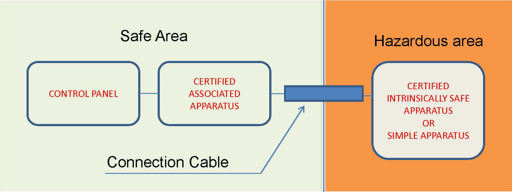
Figure 1: Example of an intrinsically safe electrical system
The 'Ex i' protection method: basic concepts
The intrinsic safety mode of protection is based on the limitation of the electrical and thermal energy of devices installed in hazardous areas to levels that prevent the ignition of an explosive mixture.
These devices, working with low energy levels, are commonly sensors for reading process parameters, such as temperatures, pressures, liquid flows, vibrations and frequencies. In recent times, with the emergence of the use of (information) networks in industrial plants, the intrinsically safe mode finds application in network nodes and input/output cards.
To understand how the intrinsically safety protection mode works, it is therefore necessary to refer to the complete electrical system [2] which is made up of various elements:
- The control panel
- The certified associated equipment
- The connection circuit
- The certified intrinsically safe circuit or, alternatively, a simple electrical construction.
Figure 1 shows an electrical system composed of these elements where both the control panel and the associated equipment are located in a safe area.
An overview of the elements of an intrinsically safe electrical system
The control panel presides over the management of a system. Due to its complexity, we can think that it is located, in most cases, outside the dangerous area or in specific compartments classified as a safe area. The signals that enter and exit the control panel cannot directly reach an area classified with industrial-type systems and protocols. In fact, although they operate with low levels of current and voltage, normal sensors are not specifically designed to limit the risk of ignition.
Here, the signals between the control panel and the danger zone are mediated by “certified associated equipment”, which is largely made up of Zener diode barriers or galvanic separation barriers.
Certified intrinsically safe circuits or, alternatively, so-called simple electrical constructions are placed in the danger zone.
The system must be considered as a whole, also taking into account how the connection circuit between the various elements is made; in fact, the interconnection cable can also store energy and the connections to earth, where present, must follow specific requirements.
The IEC 60079-14 plant standard deals with intrinsically safe circuits, distinguishing them with the particular light blue colour [3] from non-intrinsically safe circuits. Special measures are indicated to avoid simple connection errors by the operator and separation between non-'Ex i' circuits and 'Ex i' circuits.
Conclusions
Intrinsically safety is a robust and effective approach to protecting areas at risk of potentially explosive atmospheres. However, intrinsically safe equipment is only one element of a larger system that allows the management of the device itself within the imposed energy limits.
For a correct application, it must be implemented taking into account the entire system that constitutes its circuit.
Notes and bibliographical references
[1] See article “The EPL and the main methods of protection"
[2] The standard that concerns intrinsically safe electrical systems is the IEC/EN 60079-25
[3] The colour is defined in the regulations simply as “light blue” and on the market we find it mainly corresponding to RAL 5012 or, less commonly, to RAL 5015
Fecha de publicación: 23/9/2024
Tema: Additional information | Green Energy | Traditional Energy | Food | Shipbuilding | Mining | Pharmaceutical Chemist | Oil & Gas